I have been using the Articulating Pi Cam mount with my Prusa MK3S. The joints between the links were coming lose all the time, and the 3D-printed screws were breaking when I was trying to tighten them. I designed my own arm for the mount, which:
- Uses metal M3 fasteners, which can be tightened properly so that they would not come lose,
- Is more than twice lighter than the articulating arm,
- Has a slightly bigger ball for the ball joint, to make that joint a little bit tighter,
- Is compatible with the camera head from the articulating arm, so if you are already using the articulating arm, you can reuse the camera case from it.
Design Objectives
- I really liked the camera case from the Articulating Arm design, so I wanted my mount to reuse the case.
- I wanted to place the camera in a position where it can see the nozzle during the printing. This allows monitoring the print progress from the very first layer.
- I wanted the mount to have some adjustability, but, once adjusted, I wanted the adjustment to be cinched tight with a metal bolt and nut.
- I wanted to make the whole thing as light as reasonable.
Bill of Materials
My design uses:
- One 10-12 mm M3 screw, one M3 washer, and one M3 square nut (normal or thin) to attach the ball mount to the arm.
- One 6-8 mm M3 screw to attach the arm to the X axis motor.
- Camera back and cover from the Articulating Arm design (I’m including the STLs for your convenience, but if you already have them printed, you can reuse them).
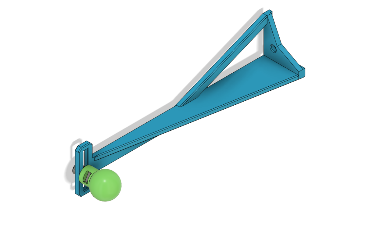
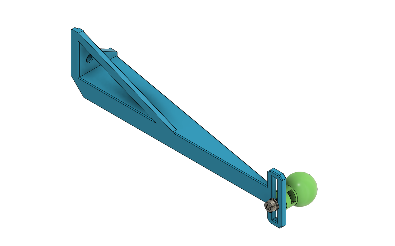
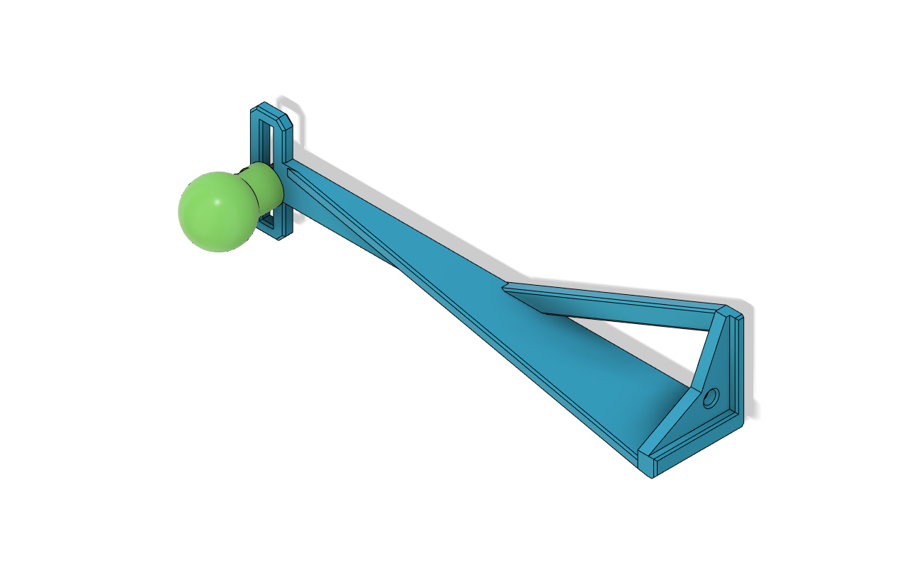
The Redesigned Arm
I made the arm design elements 3mm thin, with added edges for stiffness in all 3 dimensions. The ball mount can be fine adjusted up and down by sliding it along the mounting slot. The camera’s up/down, and left/right angles can be adjusted by rotating it on the ball mount. The only dimension that is not adjustable is the distance from the motor. There is a raised lip around the surface that contacts the motor, which prevents the arm from rotating around the mounting screw.

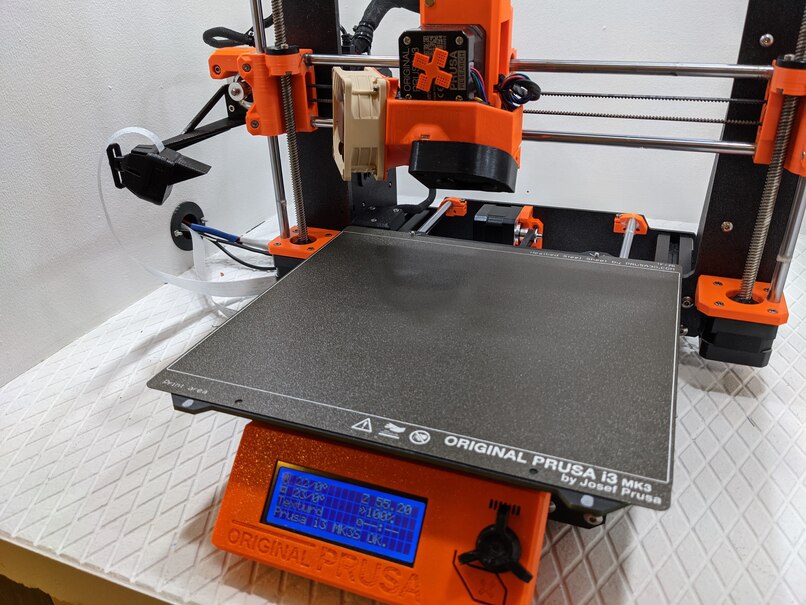
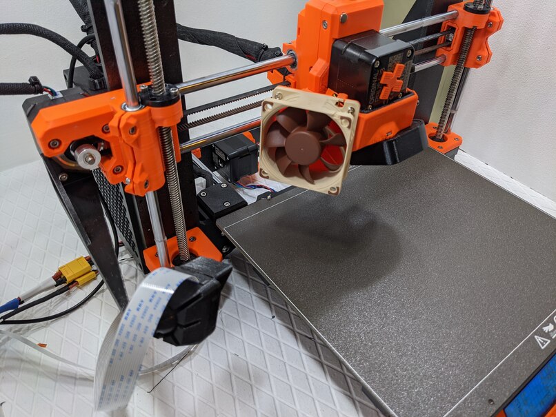
Here is what it looks like mounted on the printer:
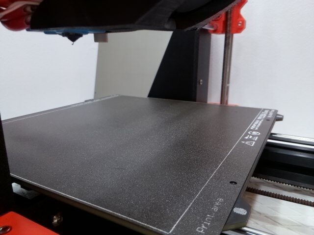
And here is a sample snapshot from the camera mounted on this mount:
The Ball Mount
I wanted the fit between the ball and the camera back to be as tight as possible, because I wanted to minimize accidental movement. I can barely shift the camera on the ball mount, which is exactly what I aimed for. However, depending on your filament calibration or preference, this fit may be too tight for you, so I’m including a slightly undersized ball mount as well.
Download STL and CAD Files
The design is released under the Creative Commons Attribution NonCommercial license. Download the zip file with the STL, STEP, and Fusion 360 files below. If you find my design useful, you can buy me a coffee.
This design on Thingiverse.
This desing on Printables.
Thanks for providing the CAD files! Going to make a version that allows the camera to be mounted even higher.
⭐⭐⭐⭐⭐ 5 Stars
I love this design, especially the fact that it moves up and down with the printer extruder! It’s an awesome idea and design.
Thank you for sharing it!
Definitely 5 stars.
I love this design, especially the fact that it moves up and down with the printer extruder! It’s an awesome idea and design.
Thank you for sharing it!